PCB transplantation of a Fluke DMM
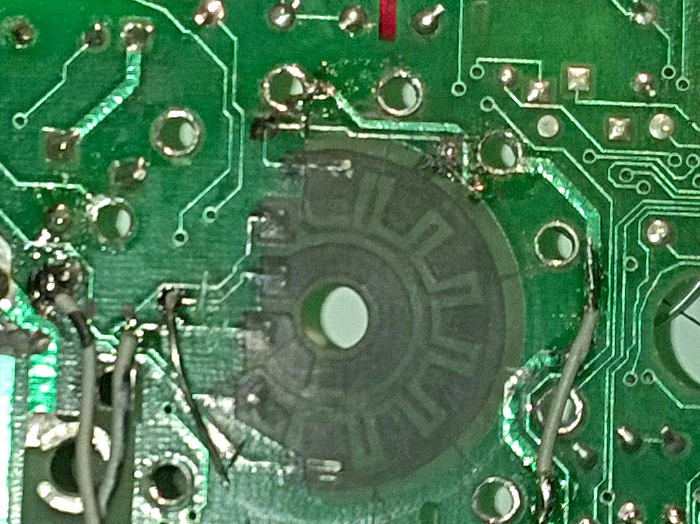
Fluke uses a resistor divider to tell the processor in what position the switch is. It is made from a sort of carbon film. At the picture above you can see it. This meter has also a problem with a partial dead IC so a nice victim to practice my PCB transplanting skills.
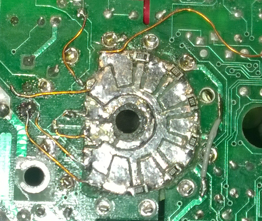
In this meter the black stuff is worn beyond cleaning, believe me I tried all the tricks from cleaning to pencil. I made a circle from very thin pcb, copied the layout from the black stuff to that. Then milled a “pocket” in the meters pcb to hold the new pcb. I made the diameter a few mm biger so there was room for resistors. Fluke changed this systemj later to one that used resistors. Glued it in place, soldered some wires to replace traces that had to go. The result was successful. It still does not measure but it now can switch into the functions.


