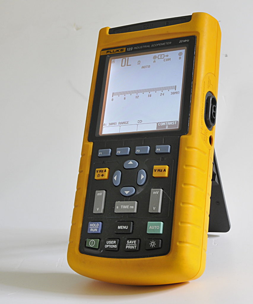
Fluke 123 scope meter
A Fluke scopemeter made in 2010. It stopped charching and turning on resulted in a few seconds before it switched off again. A new battery did not solved the problem and that is why it arrived here.
According the owner it always had some problems. The psu is nothing more as a transformer , diodes and some capacitors. The voltage is 20V but drops to 15V under load.
Be careful when replacing this psu. Fluke has the nasty habit to use the center-pin for the negative rail. Besides that the connector body is a special size. The easy way is to reuse the cable and buy a 15V powerbrick that is screwed together.
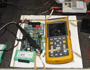
The meter is like most Flukes build to survive a lot of abuse. The problem is you need to open it like a book. That is not bad as long as you do not need to look at the other side. And the connection between the two parts is not very strong so it is easy to tear of a connector or conductor. To tackel this problem I made a simple frame to support the meter.Under the PCB and display the frame is open so it is easy to turn around and work on both sides
Een detail:
The faults were a bit unusual. It did not charge because all three current sense resistors were open. Strange because they looked normal. After solving this it worked as long as you used the psu. But not on it’s battery unless it was fully charged. So there must be an other problem.
And then the manual does not help anymore and you are on your own. Also because the manual has some faults (or is for an other version). A resistor and two testpoints are wrong. But this is easy solved with the scematic, chapter 3 and a calculator.
The cause of the problems are the smd 150uF/6,3V polymer electrolitics. For the ESR fanboys, an ESR meter was here of no use. The datasheet specs for ESR are for 120Hz (like for most caps) besides that they measured still within specs for all the parameters. There is a better way to look for cap related problems, using a scope to measure ripple. And that ripple was huge on the 3V3 rail. It looked more as AC with a small DC offset. A DMM with not enough bandwidth and crest factor would measure this as 3,1-3,2V. I replaced the caps for a version that was capable of handling more current. And this is not some magical thing, it is stated in the datasheet.
I do not know if this just was a bad series of caps or just a bad choice from the designers who are after all just humans like you and me. After that I checked all testpoints to see if there are other problem or almost problems. Then cleaning the pcbs and closing the cabinet. The final step is testing all functions and monitoring the charging over 20 hours.
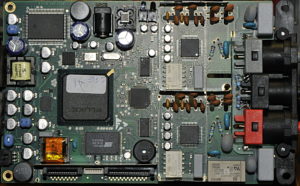
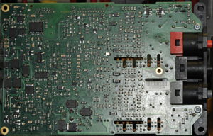
Some PCB details for the fans:

